DSL-732
Assignment 5: Electronics
Combine an input and output device together and collect data for an activity connected to you. Analyze that data and make sense of it. e.g. some examples could be displaying output from temperature/RH sensor on LCD Display to find the thermal comfort in your room, sounds of different frequencies from the Buzzer as the distance computed from a proximity sensor varies, Dustbin (full vs. half vs. empty) shows LED to be RED, YELLOW, GREEN. Please documents the steps and create a video/screenshots showing the interaction between the input and the output devices. Please also upload the codes used.
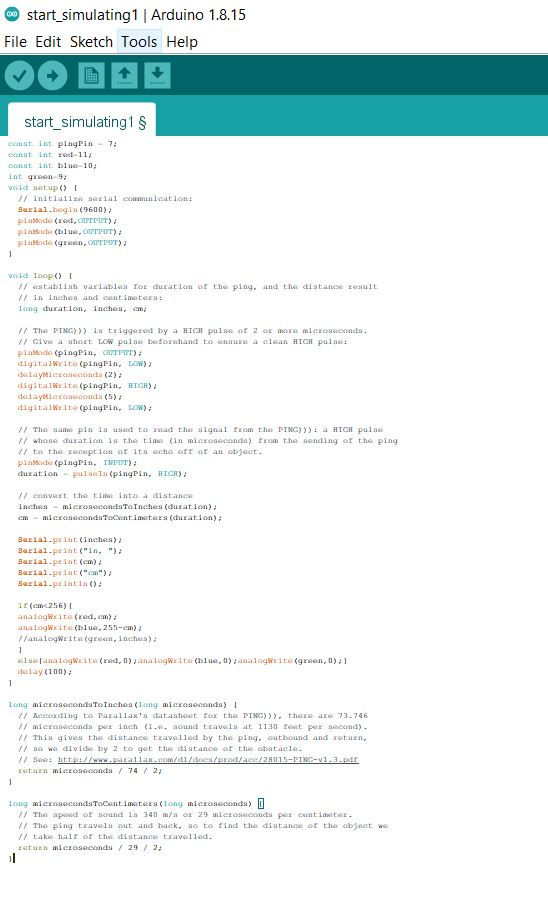
Code
const int pingPin = 7;
const int red=11;
const int blue=10;
int green=9;
void setup() {
// initialize serial communication:
Serial.begin(9600);
pinMode(red,OUTPUT);
pinMode(blue,OUTPUT);
pinMode(green,OUTPUT);
}
void loop() {
// establish variables for duration of the ping, and the distance result
// in inches and centimeters:
long duration, inches, cm;
// The PING))) is triggered by a HIGH pulse of 2 or more microseconds.
// Give a short LOW pulse beforehand to ensure a clean HIGH pulse:
pinMode(pingPin, OUTPUT);
digitalWrite(pingPin, LOW);
delayMicroseconds(2);
digitalWrite(pingPin, HIGH);
delayMicroseconds(5);
digitalWrite(pingPin, LOW);
// The same pin is used to read the signal from the PING))): a HIGH pulse
// whose duration is the time (in microseconds) from the sending of the ping
// to the reception of its echo off of an object.
pinMode(pingPin, INPUT);
duration = pulseIn(pingPin, HIGH);
// convert the time into a distance
inches = microsecondsToInches(duration);
cm = microsecondsToCentimeters(duration);
Serial.print(inches);
Serial.print("in, ");
Serial.print(cm);
Serial.print("cm");
Serial.println();
if(cm<256){
analogWrite(red,cm);
analogWrite(blue,255-cm);
//analogWrite(green,inches);
}
else{analogWrite(red,0);analogWrite(blue,0);analogWrite(green,0);}
delay(100);
}
long microsecondsToInches(long microseconds) {
// According to Parallax's datasheet for the PING))), there are 73.746
// microseconds per inch (i.e. sound travels at 1130 feet per second).
// This gives the distance travelled by the ping, outbound and return,
// so we divide by 2 to get the distance of the obstacle.
// See: http://www.parallax.com/dl/docs/prod/acc/28015-PING-v1.3.pdf
return microseconds / 74 / 2;
}
long microsecondsToCentimeters(long microseconds) {
// The speed of sound is 340 m/s or 29 microseconds per centimeter.
// The ping travels out and back, so to find the distance of the object we
// take half of the distance travelled.
return microseconds / 29 / 2;
}
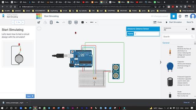
https://www.tinkercad.com/things/1f2nnjo0UjO-ultrasonic-sound-detector

https://www.instructables.com/Ultrasonic-Distance-Sensor-Arduino-HC-SR04/
Step 1: Required Electrical Components
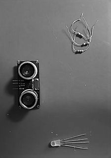
Here is a list of electrical parts one needs to complete this project
-Arduino board
-jumpers
-RGB led(I am using a common cathode but single LEDs can work as well)
-3 resistors.
-Breadboard
-HC-SRO4.
When you have all these, connect them
Step 2: Connection
Supply +5v to the breadboard from the Arduino +5v and do the same for the ground.
Mount the HC-SR04 on the breadboard. Remember from the digital electronics class the + rule vertical pins are linked together on the board rung and horizontal pins linked together in on he power rung.
Connect the sensor to the GND and +5v.
Connect the echo-pin of the HC-SR04 to pin 5 on the Arduino and trig-pin to pin 6 of the Arduino board.
Mount the LED on the breadboard. Connect resistors to the RGB pins and connect them to pin 7,8 and 9 of the Arduino respectively and connect the Cathode to ground.
Step 3: Code


Step 4: Test
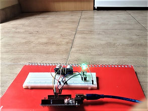
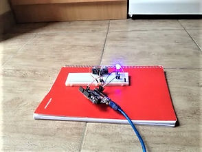
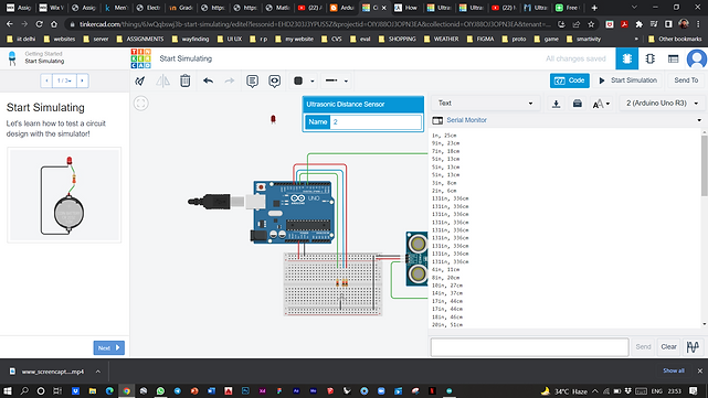
The floor in my apartment has tiles and you can see the distance from my cupboard and fridge. The LED is GREEN, and changed to BLUE when the distance was cut to half and finally RED when the sensor was really close.
